25-09-03
1.3 Main issues to be addressed in deep hole machining of difficult-to-machine materials
Based on the characteristics of deep hole machining of difficult-to-machine materials, the following issues should be noted and addressed when designing deep hole parts machining processes and selecting machining tools and deep hole machining systems.
1.3.1 Cooling, lubrication and chip removal
Since deep hole machining is difficult to dissipate cutting heat and chips are difficult to remove, forced cooling and forced chip removal measures must be adopted. Currently, high pressure is used to send cutting fluid directly to the cutting area through the outside or inside of the drill pipe. After cooling and lubricating, the chips are discharged from the inside or outside of the drill pipe to achieve the purpose of forced cooling and chip removal.
1. The role of cutting fluid in deep hole machining
(1) Cooling the tool and workpiece. Reduce thermal deformation of the tool and workpiece, improve tool durability, and ensure the dimensional accuracy of the hole.
(2) Lubricate the tool surface. Reduce friction and cutting deformation, reduce cutting force, reduce tool wear, and improve tool durability.
(3) Chip removal and vibration absorption. Use cutting fluid with a certain pressure and flow rate to flush the chips out of the cutting area to achieve chip removal. The inner hole of the workpiece and the inside and outside of the drill rod are filled with cutting fluid at a certain pressure, which can reduce the vibration and noise generated by cutting motion and friction. (4) Protect the processed surface and prevent corrosion. When using internal chip removal and front chip removal, the cutting fluid can prevent chips from scratching the processed surface and flush out fine chips, built-up edges and adhesions adhering to the workpiece surface. At the same time, it forms an oil film on the hole surface to prevent rust. 2. Selection of cutting fluid in deep hole processing Reasonable selection of cutting fluid is very important in deep hole processing and has a decisive influence on processing quality and productivity. The selection of cutting fluid mainly depends on the properties of the workpiece material, processing method, processing accuracy, type of cutting fluid and cutting conditions. The type of cutting fluid is mainly determined by its function. When friction is the main problem, a cutting fluid with good lubricity should be selected; when thermal deformation is the main problem, a cutting fluid with good cooling properties should be selected. The cutting conditions are mainly determined by the cutting speed. The higher the cutting speed, the less effective the cutting fluid becomes. Tool cooling and tool life extension should be prioritized, and cutting fluids with good penetration and low viscosity should be selected. When performing heavy cutting at low speeds, it is crucial to reduce cutting forces, improve surface finish quality, inhibit the formation of deteriorated layers, and minimize mechanical wear. Therefore, a cutting fluid with strong oil content, good lubricity, and high viscosity should be used. When performing thin cutting, the cooling capacity requirement can be lower.
The viscosity of the cutting fluid is determined by the diameter of the hole being machined. For machining small, deep holes, a low-viscosity cutting fluid is recommended to reduce viscous resistance and minimize fluid energy loss. For machining large or medium-diameter deep holes, a higher viscosity fluid can be used. The workpiece material determines the properties and composition of the cutting fluid. When the workpiece and tool materials have a strong affinity, high-pressure oils are recommended. For low-speed machining of carbon steel and low-alloy steel, fluorine-based cutting fluids are recommended. For workpiece materials with low sulfur content, pure motor oil can be used. For metals containing chromium, nickel, and tungsten, sulfur-containing cutting fluids are recommended, as they offer better lubrication and chip breaking.
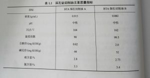
Cutting oils are commonly used in deep-hole machining, although emulsions can also be used. The main quality specifications of deep-hole drilling cutting fluids are shown in Table 1.1.
3. Cutting Fluid Flow Rate and Pressure
Properly selecting the cutting fluid pressure and flow rate is crucial in deep-hole machining. In addition to providing cooling and lubrication, the cutting fluid must have a certain pressure and high flow rate to deliver the cutting fluid to the cutting area, providing cooling and lubrication, reducing cutting temperatures, and forcing chip breaking. Furthermore, the cutting fluid must be flushed from the cutting area to the rear or front of the tool, ensuring proper chip removal. To achieve optimal surface roughness, the required operating pressure of the cooling lubricant is often higher than the pressure required for normal chip removal, and the pressure must be maintained constant.
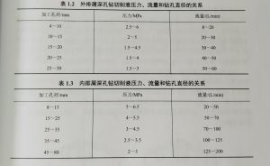
The required cutting fluid pressure and flow rate during machining vary with tool diameter, hole depth, workpiece material, and machining method. Tables 1.2 and 1.3 respectively present the relationships between cutting fluid pressure, flow rate, and hole diameter for two commonly used deep-hole machining methods. It can be seen that pressure increases with decreasing hole diameter, while flow rate increases with increasing hole diameter.
1.3.2 Chip Management
Chip removal is crucial in deep-hole machining, especially in small-diameter deep-hole drilling and trepanning, where chip removal space is limited and chip removal conditions are even more challenging, making chip removal a particularly prominent issue. Chip removal primarily involves chip handling and control, which is primarily determined by chip splitting, curling, and chip breaking. Chip width, curl shape, and chip length all directly influence chip removal.
1. Chip Allowance Coefficient R
The chip allowance coefficient R is the ratio of the chip volume a to the volume of metal removed, i.e., R = V/Vj. The chip volume coefficient R varies for different chip shapes. Generally, straight long chips have an R of -300-400; ribbon-shaped loose chips have an R of 100-300; spiral long chips have an R of 50-100; spiral short chips (including pagoda-shaped chips) have an R of 30-50; semi-annular chips (including large C-shaped chips and ribbon-shaped short chips) have an R of 15-30; clockwork chips have an R of 10-15; wrinkled unit chips have an R of 8-9; and broken unit chips (including small C-shaped chips) have an R of 5-6. The chip volume coefficient R affects the amount of space occupied by chips in the work area and, more importantly, the smoothness of chip removal and operational safety. In deep hole drilling, for internal chip removal, R < 50 generally allows for smooth chip removal. Single-edge external chip removal deep hole drills (gun drills) and trepanning drills require a smaller chip volume coefficient, i.e., R < 10, due to the small chip removal holes and channels. In order to reduce the chip volume coefficient R, chip splitting and chip breaking measures are often used, and the cutting process should be stabilized to avoid sudden changes in chip shape and irregular conditions.
2. Chip splitting measures
Chip splitting is a series of methods to divide relatively wide chips into narrower chips that are easy to curl, break and discharge. Due to the limitation of the drill rod space, the chip removal space in deep hole processing is affected by the chip removal hole area and the drill rod inner diameter area. The smallest of the two represents the size of the chip removal space. The width of the chip should be smaller than the size of the chip removal hole, generally 1/4~1/3 of the chip removal hole size, so that the chip removal is smooth. In order to achieve this goal, the chip splitting method is used in deep hole drilling to control the chip shape. The commonly used chip splitting measures are as follows.
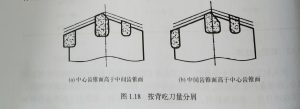
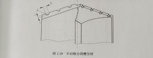
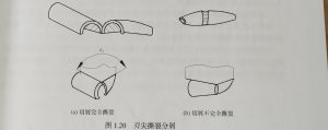
(1) Chip splitting by back cutting amount: that is, chip splitting by the width of the cutter teeth. The relative position between the cutting edges of each cutter tooth (cutter tooth height and width) needs to be reasonably distributed and controlled so that thick and narrow chips can be formed during processing, as shown in Figure 1.18. When manufacturing the tool, the cutting edges are placed on different conical surfaces, and the different conical surfaces differ in axial feed rate. At this time, the relative positions of the tooth height and width between the cutting edges need to be reasonably designed to form a stepped cutting edge. This chip-splitting method is relatively simple to manufacture and sharpen, with low cutting force and torque, and relatively stable operation. (2) Asymmetric chip-splitting groove: It is mainly used for high-speed steel tools (such as flat drills) when the cutting speed is low and the feed rate is not large, as shown in Figure 1.19. It should be noted that the chip-splitting groove cannot be ground too deep or too shallow. If it is too deep, point A will be weak and wear will be fast; if it is too shallow, it is difficult to ensure reliable chip-splitting. Generally, the depth c = 0.5~0.8mm and the width b = 1~1.5mm are used. (2) Blade tip tearing chip-splitting: It is mainly used for gun drills. When the tip angle & of the inner and outer cutting edges is small, the inner and outer cutting edges can be chip-split, as shown in Figure 1.20. However, this chip splitting method is not very reliable. Due to the long cutting distance, the blade wears and becomes blunt, which weakens the chip splitting effect of the blade. At this time, the chip is not in the chip splitting state at the beginning, as shown in Figure 1.20(a), but curls in the plane perpendicular to the blade, and produces a certain lateral deformation, and the chip is completely torn. As shown in Figure 1.20(b), the blade wears and becomes blunt, the lateral deformation decreases, and the chip is not completely torn.
(3)
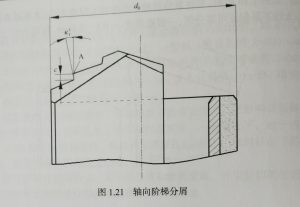
(4) Axial step chip splitting: The chip is split by staggering the blades in the axial direction at different depths, as shown in Figure 1.21. As long as the depth c is greater than the feed rate f, the chip splitting is reliable. When c is 4 to 5 times the feed rate, the chip splitting effect is better. Generally, c=1 to 1.5mm is used for drilling and c=1.6 to 2mm is used for trepanning. At the same time, the c value can be smaller at the outer edge of the drill bit, while the c value near the core is larger, because the cutting speed is low in the core, the chip deformation is large, the chip thickness increases, and it is difficult to split the chip. When grinding the step, pay attention to grinding the secondary deflection angle (x’~5°) and the secondary clearance angle (α) = 5° at each section of the secondary cutting edge, otherwise it will cause rapid wear of the tip A point.